
EVER JOY / CONVEYOR COMPONENTS
Conveyor Drum Pulleys
Drive, Bend & Lagged Pulleys
Drive, bend, tail, take-up and lagged pulleys for bulk-material belt conveyors
- Drawing-based supply
- Bearing housings available
- Plain or lagged shells
- Export packing support
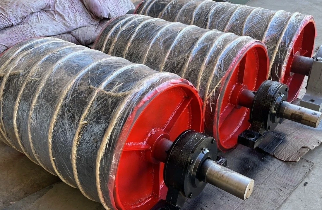
1. Product overview
EVER JOY supplies drive, bend, tail, take-up and lagged drum pulley assemblies for belt conveyor systems. These components transmit drive torque, redirect the conveyor belt or work with the take-up arrangement.
Pulley selection requires more than belt width and drum diameter. Confirm the belt construction and rating, bare-shell diameter, face width, belt tensions, shaft geometry, bearing centers, lagging, wrap angle and speed.
2. Pulley types and functions
These terms describe either function or surface construction. A head or tail pulley may also serve as a drive or bend pulley, depending on the conveyor layout.
| Pulley type | Function and selection notes |
|---|---|
| Drive pulley / Drive Pulley | Receives torque from a drive unit to move the belt. Design against belt tensions, wrap angle and shaft torque. |
| Bend pulley / Bend Pulley | Changes belt direction. Size for wrap angle, resultant belt pull and bearing geometry. |
| Tail pulley / Tail Pulley | Located at the tail to guide the return path; may be integrated with a take-up design. |
| Take-up / snub / Take-up / Snub Pulley | Take-up pulleys work with tensioning systems; snub pulleys change the wrap on a drive pulley. |
| Rubber-lagged pulley / Lagged Pulley | Plain, diamond, chevron-groove or ceramic surfaces can be specified for suitable applications. |
| Wing pulley / Wing Pulley | Open-wing construction helps shed material where the conveyor design permits; unlike a solid drum. |
3. Shell surfaces and construction options
| Surface | Selection considerations |
|---|---|
| Plain steel surface | For positions selected by engineering calculation; reassess friction when moisture or debris is present. |
| Rubber lagging | Provides a tailored contact surface; specify thickness, hardness, compound and bonding process. |
| Grooved / diamond / chevron lagging | Choose geometry for drainage and operating conditions; a pattern alone does not guarantee traction. |
| Ceramic lagging / wing design | Project-specific options for abrasion or build-up conditions; confirm belt compatibility. |
4. Pulley construction and dimensions
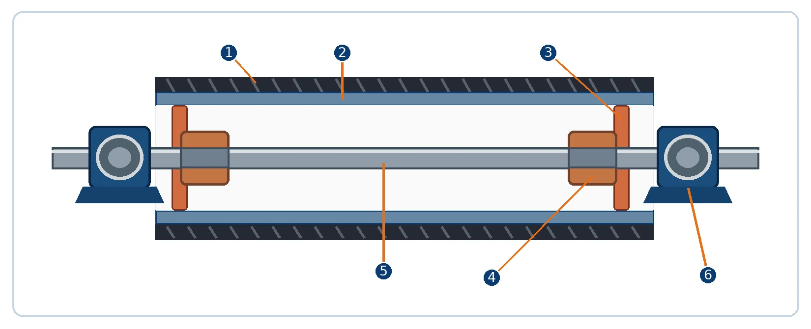
| No. | Component | Function |
|---|---|---|
| 1 | Lagging | Optional rubber or ceramic outer layer |
| 2 | Shell / rim | Steel contact cylinder supporting belt load |
| 3 | End disc | Transfers shell loads toward the hub and shaft |
| 4 | Hub / locking joint | Welded or locking connection as specified |
| 5 | Main shaft | Carries bending loads and, for drives, torque |
| 6 | Bearing housing | External support with defined mounting layout |

5. Technical specifications and series selection
| Item | Specify when ordering |
|---|---|
| Pulley duty / series | Drive, bend, tail, take-up or snub; TD75, DTⅡ or machine-specific drawing |
| Diameter D | Bare steel outside diameter; finished OD separately when lagged |
| Face width F | Actual drum face length; not the same as conveyor belt width |
| Shaft / bearings | Shaft overall length S, bearing center distance C, housing series and bolt positions |
| Shaft ends | Diameter d, shoulders, extensions, keyways, coupling and drive side |
| Construction | Shell thickness, end discs, hub connection, shaft material, weld specification |
| Lagging | Plain, diamond, chevron-groove or ceramic; material, thickness and bonding |
| Operating load | Belt rating, tensions T1/T2, wrap angle, speed, duty and environmental conditions |
| QC / delivery | Agreed tolerances, runout, balance, welding checks, packing, quantity and port |
TD75 — selected pulley diameter combinations (mm)
| Belt B (mm) | Drive ØD (mm) | Bend ØD (mm) |
|---|---|---|
| 500 | 500 / 630 | 250 / 315 / 400 / 500 |
| 650 | 500 / 630 | 250 / 315 / 400 / 500 |
| 800 | 500 / 630 / 800 | 250 / 315 / 400 / 500 / 630 / 800 / 1000 |
| 1000 | 630 / 800 / 1000 | 250 / 315 / 400 / 500 / 630 / 800 / 1000 |
| 1200 | 630 / 800 / 1000 | 250 / 315 / 400 / 500 / 630 / 800 / 1000 |
| 1400 | 800 / 1000 | 250 / 315 / 400 / 500 / 630 / 800 / 1000 |
DTⅡ(A) drive pulleys — published design examples (mm)
| Belt width B (mm) | Shell ØD × face F (mm) | Rated torque (kN·m) | Rated resultant (kN) |
|---|---|---|---|
| 500 | 500 × 600 | 2.7 | 49 |
| 650 | 500 × 750 | 3.5 | 40 |
| 800 | 500 × 950 | 4.1 | 40 |
| 800 | 630 × 950 | 6.0 | 50 |
| 1000 | 630 × 1150 | 6.0 | 40 |
6. Quality control, standards and acceptance
Inspection requirements must correspond to pulley geometry, duty, contract and applicable standards. The list below describes items to agree—not a claim that every pulley has the same test report.
| Inspection item | Checks / acceptance agreement |
|---|---|
| Dimensions and geometry | Diameter, face length, shaft extensions, mounting dimensions and fits |
| Runout / concentricity | Check to the agreed diameter, speed and engineering acceptance limits |
| Static / dynamic balance | Set requirement and grade according to rotational duty and contract |
| Welds and NDT | Document welding procedure and any specified critical-weld examination |
| Shaft and bearings | Material, bearing designation, fits, lubrication and rotation |
| Lagging quality | Thickness, bonding, surface finish, grooving and visual defects |
| Coating and packing | Corrosion protection, marking, shaft-end protection and export packing |
Applicable engineering references
| Standard | Applicable scope |
|---|---|
| GB/T 10595-2017 | Belt conveyors: applicable pulley, inspection and system requirements |
| ANSI/CEMA B105.1-2021 | Selection guidance for welded steel pulleys with compression-type hubs, where applicable |
| ANSI/CEMA 501.1-2021 | Welded steel wing pulleys, only when the wing-pulley design applies |
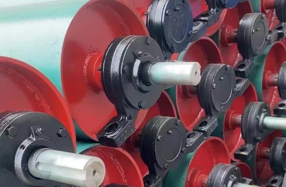
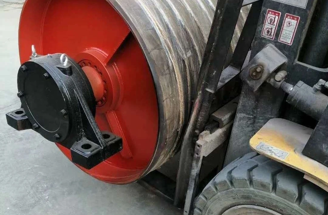
7. Applications and actual product photos
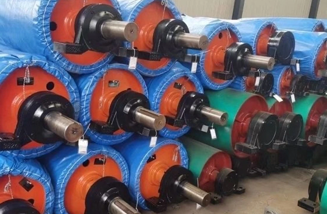
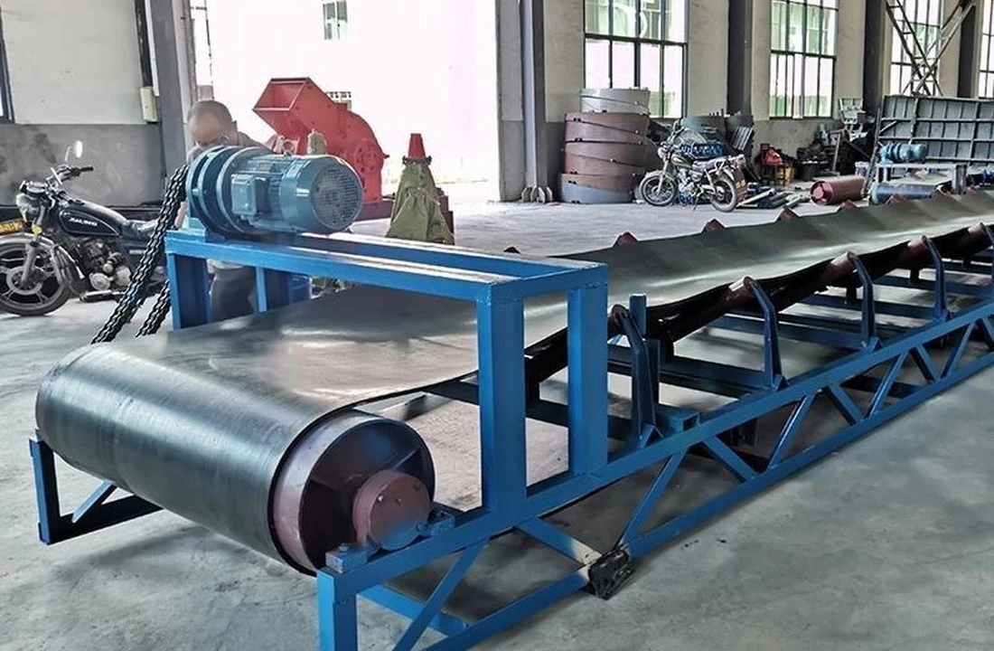


| Industry | Selection considerations |
|---|---|
| Mining and aggregates | Heavy belt loads, abrasion, dust and bearing-seal conditions. |
| Cement and steel | Dust, heat exposure, corrosion and continuous operation. |
| Ports and terminals | Moisture, salt exposure, traction and maintainability. |
| Conveyor retrofits | Match the original pulley, frame, drive and take-up drawings. |
8. Manufacturing and export support
EVER JOY supports technical specification review, customized pulley supply and export delivery for overseas conveyor projects. Production is based in Guzhen County, Bengbu, Anhui, China. Packing protection and delivery documents can be agreed per order.
9. Buyer FAQs and inquiry checklist
01 Is belt width enough to order a pulley?
No. At minimum provide drum diameter, face width, shaft mounting drawing and duty. Drive pulleys also need belt tensions, wrap angle and speed.
02 Are TD75 and DTⅡ pulleys interchangeable?
Not by belt width and diameter alone. Confirm shaft overall length, bearing centers, mounting holes, shaft ends, torque and drive layout.
03 Does diameter include the lagging?
Specify bare-shell diameter and finished outside diameter separately, plus lagging thickness and groove profile.
04 How is overall shaft length decided?
From bearing position, shaft shoulders, coupling, drive fitting and conveyor frame geometry; confirm against the original drawing.
05 Can lagging patterns be customized?
Plain, diamond and chevron grooves can be discussed subject to compound, thickness, bonding and inspection agreement.
06 Are pulleys supplied with bearings/housings?
Pulley, shaft, bearings and housings can be coordinated according to the drawing; confirm the exact scope on the quotation.
07 Is dynamic balancing necessary?
It depends on speed, diameter, mass and duty. State the required balancing grade for fast or large drums.
08 Can inspection records be supplied?
Inspection and shipment records may be defined in the order for dimensions, welds, runout and lagging; do not rely on generic certificates.
10. Information required for an accurate quotation
- Pulley duty and conveyor series (TD75 / DTⅡ / custom drawing)
- Belt width/rating, speed, tensions T1/T2, wrap angle and environment
- Bare drum diameter D, face width F, shaft overall length S, bearing centers C
- Shaft ends, keyways, housing mounting and preferred drive side
- Lagging material, thickness, profile, quantity and destination
- Photos, nameplate, original pulley or conveyor equipment drawings
 English
 Spanish